
Most of the time, there are cooling ribs in the frame of the motor, and you will use clamps to fix the SMS to the motor. For motors whose housing does not have cooling ribs, contact your ADI Sales representative to purchase a specially designed base for the installation of the SMS.
If you are using clamps to fix the SMS to the motor:
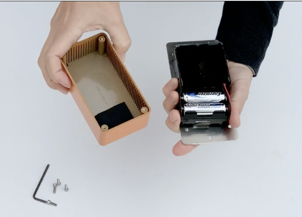
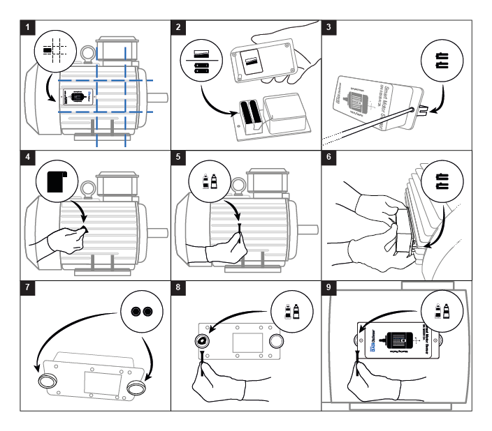
- 1. Make sure the batteries are installed in the device and put the case back on, verify that the foam area covers the battery holder – Fig 2.
![]()
![]()
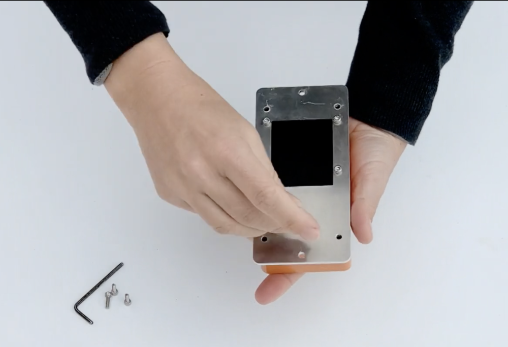
- 2. Screw the fixing clamps on the base of the device. Make sure they do not exceed beyond the edge of the SMS. Don’t completely tighten at this time – Fig. 3.
![]()
![]()
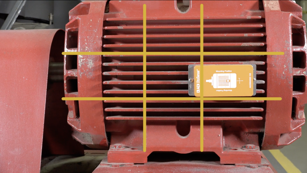
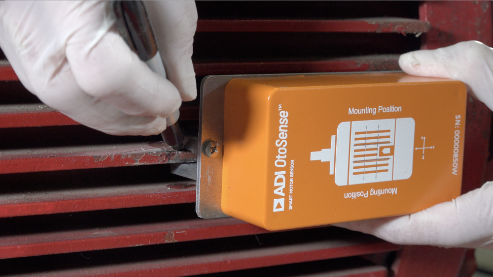
- 3. Place the device in the back-center area, as shown in the sketch on the SMS case (respect these indications whether the motor is in a vertical or horizontal position) and mark with a pen on the fins where the clamps will be placed – Fig.1.
![]()
![]()
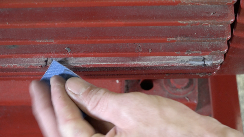
- 4. Next, sand the surface where the device will be fitted to remove the paint. This surface preparation will improve adhesion – Fig. 4.
![]()
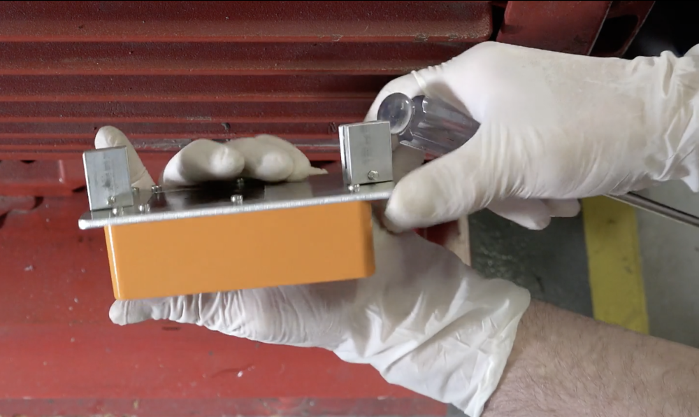
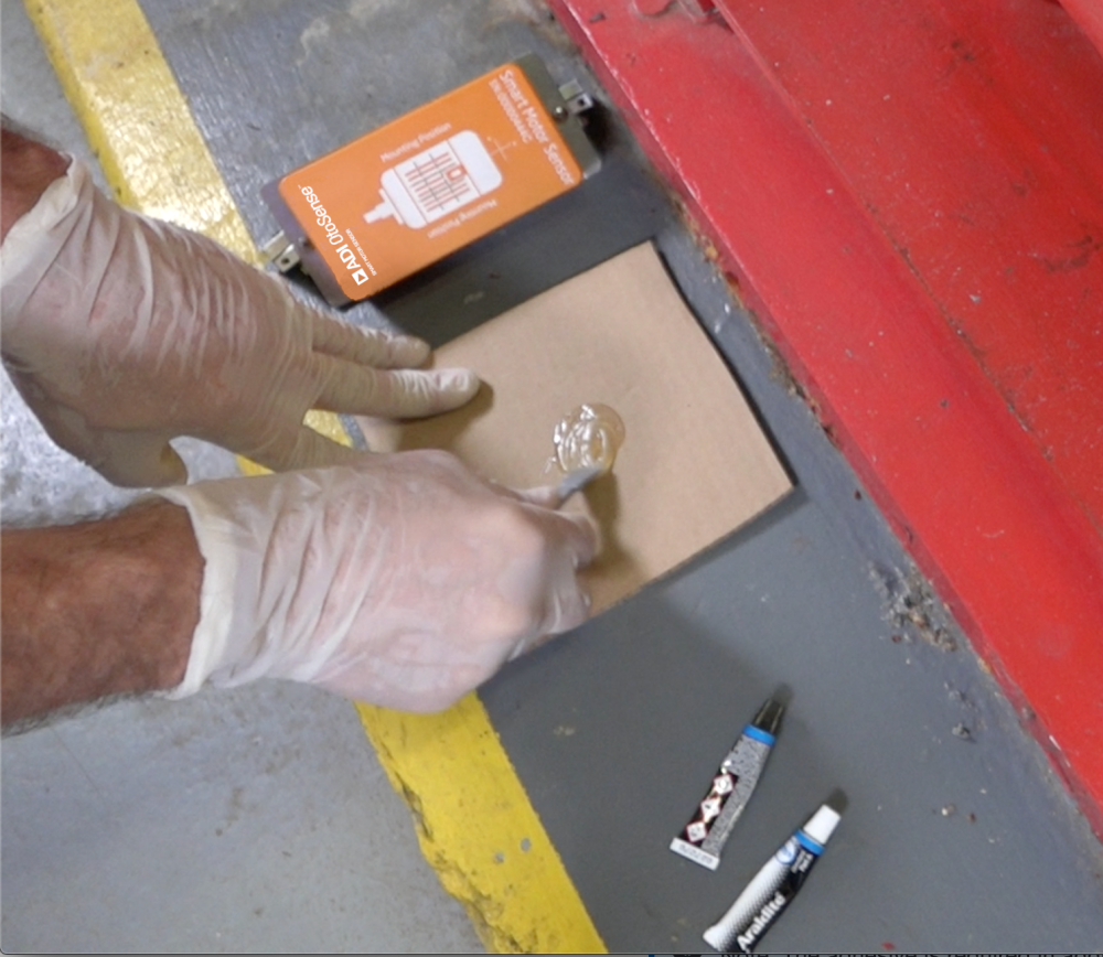
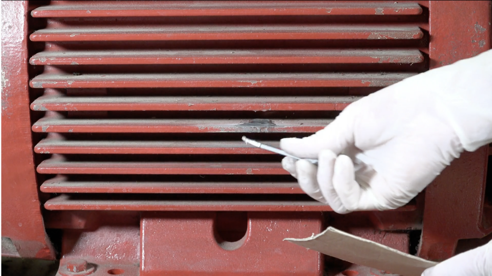
- 5. Make the mixture of the bi-component adhesive on a piece of cardboard. Place adhesive on both sides of the cooling fin in the sanded area where the clamps are to be placed – Fig. 5.
![]()
![]()
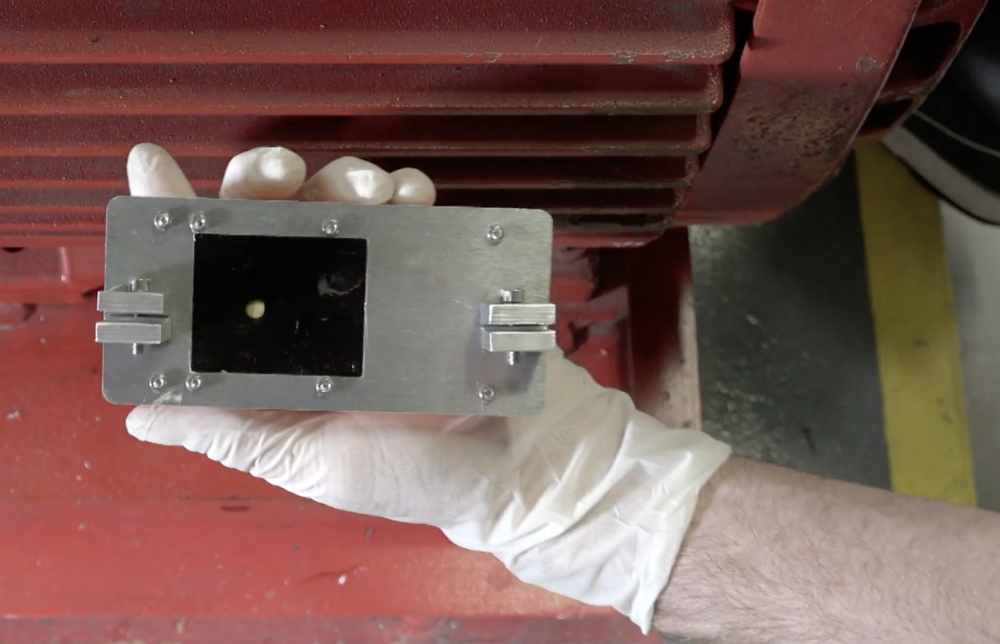
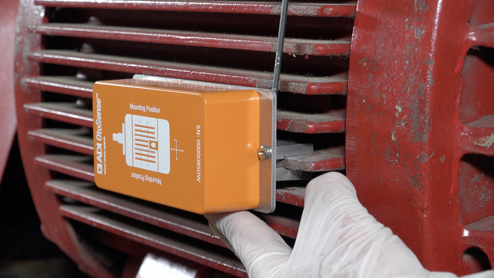
- 6. Place the device on the cooling fins using the fixing clamps. Please take note of the orientation of the device with respect to the motor as indicated on the case – Fig. 6
![]()
- 7. Tighten the screws on top of the clamps using an Allen Wrench. Using a Philips screwdriver finish tightening the screws to secure the SMS to the clamps.
![]()
If your motor doesn’t have cooling fins
- You will need to use a magnetic base – Fig. 7.
- Screw the magnetic base to the base of the device.
- Place the device in the back-center area, as shown in the sketch on the SMS case (respect these indications whether the motor is in a vertical or horizontal position) and mark with a pen where magnetic base will be placed – Fig.1.
- Next, sand the surface where the device will be fitted to remove the paint. This surface preparation will improve adhesion – Fig. 4.
- Mix the bi-component adhesive mixture and apply it to the magnetic base – Fig. 8
- Fix the device using the magnetic bases with the bi-component adhesive to the motor housing.
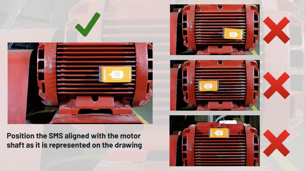
Dos and don’ts
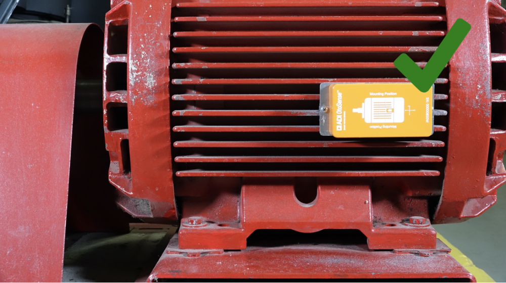
Correct installation of the SMS. Note that depending on the size of the motor, the SMS will take up more more surface than what is shown in the sketch on the SMS case.
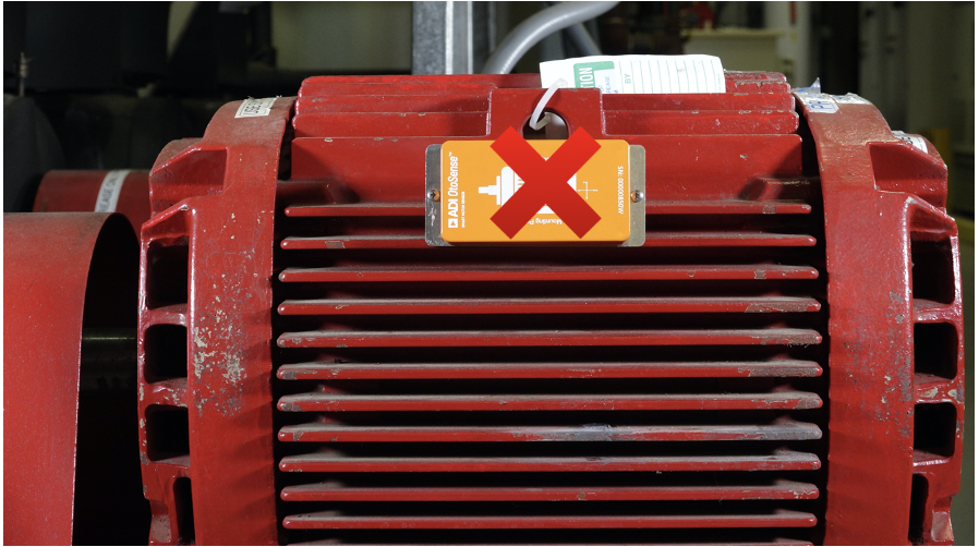
Device is not placed in the back-center area
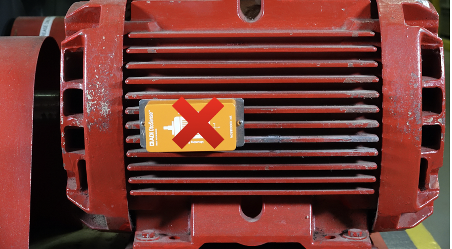
Device is not placed in the back area (in regards with the shaft of the motor)
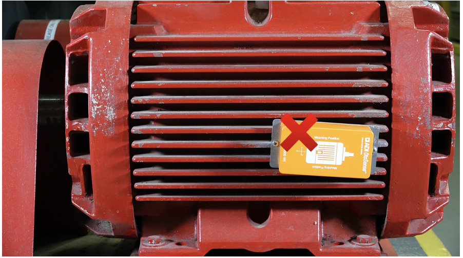
Device is not parallel with the cooling fins and it is laterally-inverted, in relation to the motor shaft. The motor shaft in the sketch must point in the same direction as the real motor shaft.